
 Online Services
 Application Inquiry
 Pay Assurance Fee
 Query Installation Number
 Compensation Fee Inquiry
 Automatic Payment Order Inquiry
 Partnership
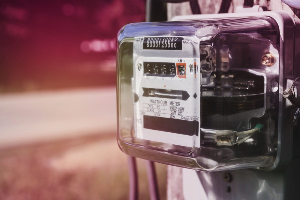
What is an Electricity Meter? How does an Electricity Meter Work? Electricity Meter Types
What is in this article?
Measuring electricity consumption is of great importance due to limited energy resources. Electricity meters are devices that measure the amount of electricity consumed or generated.
Today, thanks to digitalized meters that automatically transmit data, it is easier to determine consumption.
Here you can find all the information you are interested in about electricity meters, multi-period and single-period electricity tariffs.
What Is an Electricity Meter and How Does It Work?
Devices that measure the amount of electrical energy consumed or generated are called electricity meters. The energy consumed is measured in kilowatt-hours (kWh) and the clock is used as a time zone in this measurement. The symbol for the electricity meter is kWh.
Electricity meters can measure not only energy consumed, but also capacitive consumption (current higher than voltage), inductive consumption (voltage higher than current) and tariff consumption. The capacitive and inductive consumption, which indicates reactive use i.e. how much energy some devices need to come on line, must be between certain values.
Certain penalties may be imposed on consumers who exceed this value, which is set by the electric utility companies. In the tariff-based subscription, which requires the use of digital electricity meters, the consumption costs are determined according to the time zone in which the energy is consumed.
Energy consumed in areas such as homes, workplaces, power plants, shopping malls, and industrial plants is metered and billed by electric utilities using meters. Energy consumption can be reduced by choosing high efficiency energy class products.
All meters used in Turkey must comply with the specifications for electronic meters published by the Turkish Electricity Distribution Corporation (TEDAŞ). The standards set in the specification ensure that data transmissions are correct and that the amount of energy consumed is measured correctly.
Electricity Meter Operating Logic
 Electricity meters have different operating modes depending on the circuit type and structure. The current and voltage coils in mechanical meters generate a magnetic field and cause the meter disk to rotate.
The meter to which the disc is connected rotates with the disc and measures the current flowing through the circuit.
We can speak of a similar process in electronic meters, but unlike mechanical meters, the current and voltage passing through the circuit are measured simultaneously.
Electronic circuits convert this information into numerical data and determine the amount of electrical energy consumed.
Types of Electricity Meters
Types of electricity meters: They are distinguished according to the type of circuit, the type of connection to the grid, the structure, the type of connection to the circuit, the time and the type of energy used.
Meters by Circuit Type
According to the circuit type, meters are divided into two as AC meters and DC meters:
-
AC Meters
Meters in which the current flowing through the circuit used is alternating current (AC) are called AC meters. In AC meters, the electrons move in a variable direction.
-
DC Meters
DC meters are meters where the current flowing through the circuit is direct current (DC). In DC, the electrons move in one direction.
Meters According to the Way They are Connected to the Circuit
Meters are divided into secondary (direct) and primary (x/5) depending on how they are connected to the circuit:
-
X5 Meters
These meters are connected to the circuit through current transformers or current and voltage transformers. The reason why it is also called X5 is that it works with a reference current of 5 amps. A current transformer is used for low voltage, and a current and voltage transformer is used for medium voltage.
-
Direct Connected Meters
Direct connected meters are connected directly to the circuit. To make this connection, the electrical load must be at least 100 amps. The absence of a transducer is one of the most important features of these meters.
Meters by the Type of Connection to the Network
Depending on the type of connection, meters are divided into single-phase, or three-phase meters. Although phase literally means stage or any of the variables, it describes the state of the vectors indicating the alternating current in an electrical circuit relative to the X axis.
-
Single Phase Meters
Single-part induction meters, also called single-phase and two-wire meters, consist of a disk, current and voltage coil, meter, and magnet. As the discs rotate due to the pulse generated by the coils, the counter also rotates.
While the magnetic field generated by the voltage coils connected in parallel with the circuit remains constant, the magnetic field changes when current flows through the current coil. A phase difference is created between these magnetic fields, allowing the meter disk to rotate. The speed of rotation of the disk can be slow or fast, depending on the current.
-
Three-Phase Meters
Three-phase meters are obtained by combining two or three single-phase meters. The only difference from single-phase meters is that more than one disc rotates on the shaft. Depending on the number of conductors coming from the mains, they are categorized as three-wire and four-wire meters:
- Two-element three-phase three-wire meters(Aron connected meters): These meters can be used with neutral conductor when the electrical load is balanced. These meters have two current and voltage coils. Since it cannot measure the electrical energy of a third phase, it can only be used in three-phase and balanced systems.
- Triple three-phase four-wire meters: In cases where the energy of each phase must be measured separately, 2.5 or 3 element three-phase four-wire meters are used. In these meters, each end of the current coil is connected in series with the phase, while the ends of the voltage coil are connected in parallel between the neutral and the input of the phases.
Meters According to Their Structure
Meters are divided into two according to their working structure: mechanical (induction meters) and electronic (digital meters):
-
Mechanical Meters
 Single-phase and three-phase types of mechanical meters consist of voltage coil, current coil, magnetic bearing, counter, gears and disks. Current coils with low winding resistance are wound with thick conductor cross-section and have few windings (low number of turns). Voltage coils with large resistance are wound with a thin conductor and have many windings. While current coils are connected in series, voltage coils are connected in parallel.
The disks are located between the current and voltage electromagnets, which are perpendicular to each other. The voltage and current coils exert force on the disks in the mechanical part of the meter. This force causes the disk, which is a moving part, to rotate, and this motion continues as long as the current continues.
The counter, which determines the number of cycles of the disk, acts like a clock in the counter. Since the rotating disk also turns the meter, the energy consumed can be measured. Today, as mechanical meters are gradually being replaced by digital meters, the range of applications for these meters has decreased.
-
Electronic Meters
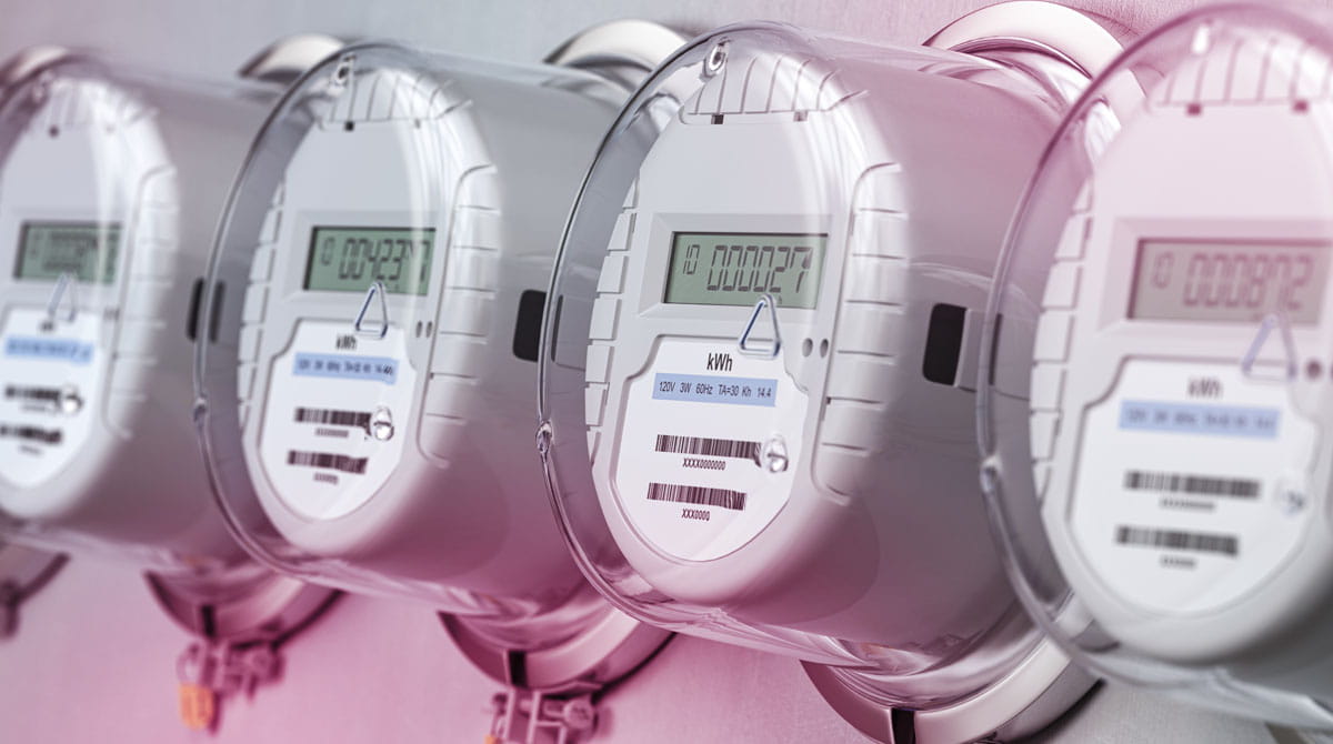 Electronic or digital meters are devices that have technological functions and can make precise measurements. Although they are similar to mechanical meters in terms of their connection to the circuit, the principle of operation of these meters is different. There is a signal processor or microprocessor in these meters. These meters can be charged at different times of the day or differently depending on the day.
Various parameters such as time, date, tariff, reactive power, active power are automatically stored in the signal processor. A. Both users and power companies can see the recorded data through LCD displays on the meter.
The optical port (optical reader) in some digital meters allows wireless data transmission of the products. All data can be transferred to the computer through this port. Thus, even data from past periods regarding consumption can be checked later.
To prevent unauthorized use and ensure security, the number of openings of the box can be traced thanks to the tamper device located under the terminal box (the box that contains the connection points of the electrical cables).
Meters by Time
For some meters, the calculation of the amount of electricity consumed is based on the time period. In this sense, the meters are divided into two categories: single time and multi-time:
-
Single Time Meters
Single time meters, which are generally mechanical, apply a single tariff. The energy consumed by users is charged according to a fixed tariff.
-
Multi-Time Meters
In multi-time meters, the energy consumed at certain times of the day is charged at different unit prices. In our country, different tariffs apply depending on the three different time zones. In order to collect and read data from multi-time meters, the meter structure must be electronic.
Meters by Type of Energy
According to the type of energy used, meters are divided into active, reactive and combination:
-
Active Meters
Active meters are devices that actively measure consumed electrical energy and are generally used in small businesses.
-
Reactive Meters
Reactive meters, generally used in businesses, are used to measure reactive power. The reason for using these meters in industrial facilities is that the reactive power consumed is very high compared to residential facilities due to the large number of transformers and motors.
-
Active/Reactive (Combination) Meters
Active/reactive meters, also called combination meters, can make both active and reactive measurements. These meters are characterized by measuring at high currents and providing more accurate results without current transformers.
Which Meter Is Used in Homes?
Single-phase / two-wire active consumption meters are usually used in residential buildings. Most homes use electronic meters with automatic metering, but in very old buildings the meters may still be mechanical.
How Do I Read the Electricity Meter?
When measuring with single-phase mechanical electricity meters current and voltage coil terminals are used. The phase goes into the current terminals, and the neutral line goes into the voltage terminals. The phase goes to the floor panel of the houses and the neutral is led from there to the installation. The measurement and reading of the electricity meters is also based on this data.
The electronic meters in use today use optical portsto measure consumption. Most households and businesses are connected to a centralized automatic meter reading system. Since the data from the electricity meter is collected automatically, it is relatively easy to determine the amount of consumption.
One of the advantages of the communication infrastructure with optical ports is that it enables cost-effective galvanic isolation between the readers and the network.
In Turkey, electricity meters are read according to electricity consumption between 25-35 days. Users have 10 days from the reading date for final bill payment.
Does the Type of Electricity Meter Affect the Bill?
Depending on whether the meter is mechanical or digital, prices may be different. Since mechanical meters use a single rate, the monthly charge is fixed.
With electronic meters, users can choose tariffs depending on their consumption habits. At this point, the time period in which the electricity is consumed is important. Those who want to save electricity can switch to multi-tariff systems, which require the use of digital meters.
How to Connect the Electricity Meter to the Circuit?
In order to accurately measure the amount of electrical energy consumed, the first thing to consider is the proper connection of the meter. The meter can be connected to the circuit directly or with a current transformer. The voltage coil, which is the basic element of the electricity meter, is connected in parallel with the circuit, while the current coil is connected in series.
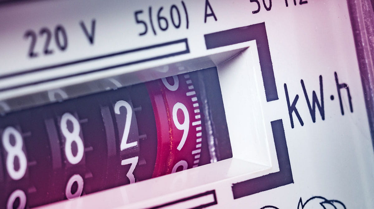
Direct connection is preferable when the power of the receiver is low. In single-phase circuits 220 volts are connected, in three-phase circuits 380 volts. The electrical load must not exceed 100 amps. Electricity meters, generally used in residential buildings, are connected directly to the circuit.
The current transformer can change the magnitude of the current. It enables the reduction of primary currents by coupling (by transmission) and transfers them to the secondary circuit, the second circuit. In this way, the circuit elements are protected from voltage and high current. In industrial areas such as factories and workshops, the connection is usually made through a transformer. In high-voltage electrical installations, current and voltage transformers can also be used.
When connecting the meters to the circuit, it is ensured that the current and voltage are from the same phase and whether they are internal or external, and the phase sequence must be observed.
What Does an Electricity Meter Do?
The devices used in almost every residence and workplace are responsible for measuring the amount of electricity passing through the meter. The amount of electricity consumed by users during a period determined by utility companies is measured by these devices and pricing is made accordingly.
Where Was the Electricity Meter First Used?
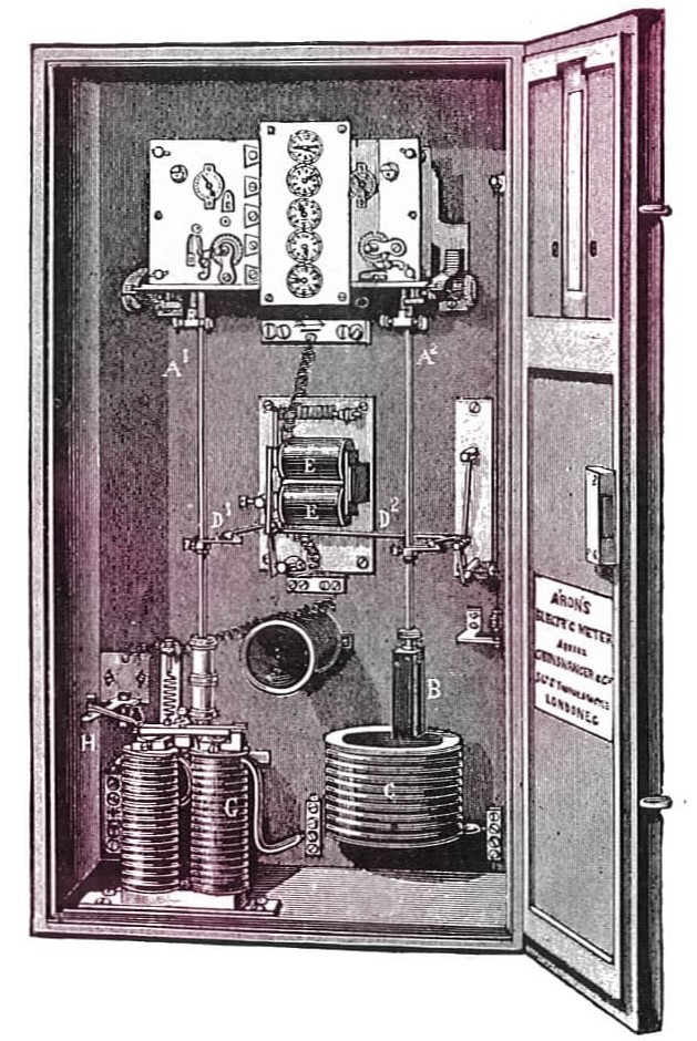
The patent for the first DC meter to measure the amount of electricity consumption was granted to Dr. Hermann Aron in 1883. This meter was started to be used commercially in Great Britain in 1888 by the General Electric Company under the leadership of Hugo Hirst.
The devices, which recorded the electrical energy consumed in a certain period of time, allowed users to see the amount of consumption on a display.
Hungarian Ottó Bláthy patented the first AC electricity meter. For this reason, the first meters using alternating current are named after Bláthy.
The first AC commercial meters developed on the basis of this meter were introduced by the Ganz Works company at the Frankfurt Fair in 1889 and put on sale at the end of the same year.
What Is a Tariffed Electricity Meter?
Tariffed electricity meters are devices that allow the pricing of the energy used to be made according to certain times of the day. In the tariffed system, which contributes to the reduction of the bill, the pricing of the amount of energy consumed is made according to the time period. Tariffed electricity meters have three different time zones:
- 06.00 - 17.00 (Daytime consumption)
- 17.00 - 22.00 (Peak or evening consumption)
- 22.00 - 06.00 (Night consumption)
According to these time zones, the unit price per 1 kWh consumption is different. The peak or evening time zone has the highest unit price among these three time zones. The consumption charge (total kWh used) is calculated by subtracting the first index (the value at the last billing date) from the last index (the value at the last meter reading).
The purpose of tariffed meters is to restrict the use of high-power devices only during peak times. In this way, overloading of distribution lines and malfunctions are prevented, while use is encouraged during day and night hours when electricity consumption is low.
Which type of meter do you use in your home and at which time of the day do you use your electrical appliances more? You can share with us in the comments.


Leave a Comment